3D MACROS

This macro creates a new 2D sheet drawing with the flat view of a sheet metal part without bends (plate).
How to use: This macro creates a new 2D sheet drawing with the flat view of a sheet metal part without bends (plate).
This macro creates a new 2D sheet drawing with the flat pattern view of the current 3D sheet metal part.
How to use: Select the reference face and press [YES] to mark the bends, [NO] to use the flat command or [CANCEL] to only create the 2D drawing (when the part was already unfolded). The flat pattern view will follow the configuration of your favourite template.
This macro creates a new 2D drawing which is composed by 2 sheets: the first one with the 4 main views (3+isometric one) the flat pattern view scaled 1:1 and bend datas, the second one is an empty sheet on the which a clean falt pattern view (without bend datas) will be added.
How to use:  it is enough to run the macro, select the solids and set the rule..
How to use:  select the reference face and press [YES] to mark the bends, [NO] to use the flat command or [CANCEL] to only create the 2D drawing (the part was already unfolded). The flat pattern view will follow the configuration of your favourite template.
This macro creates a new 2D drawing in the which the 4 main view will be added. The 3D model can be a single shape or an assembly composed by solids.
How to use:  select the solid you are interested in, ZW will open this part in a new external Z3PRT and it waits for the user to select the reference face for the main view
These are 4 commands to automatically create one or more joints between 2 solids:
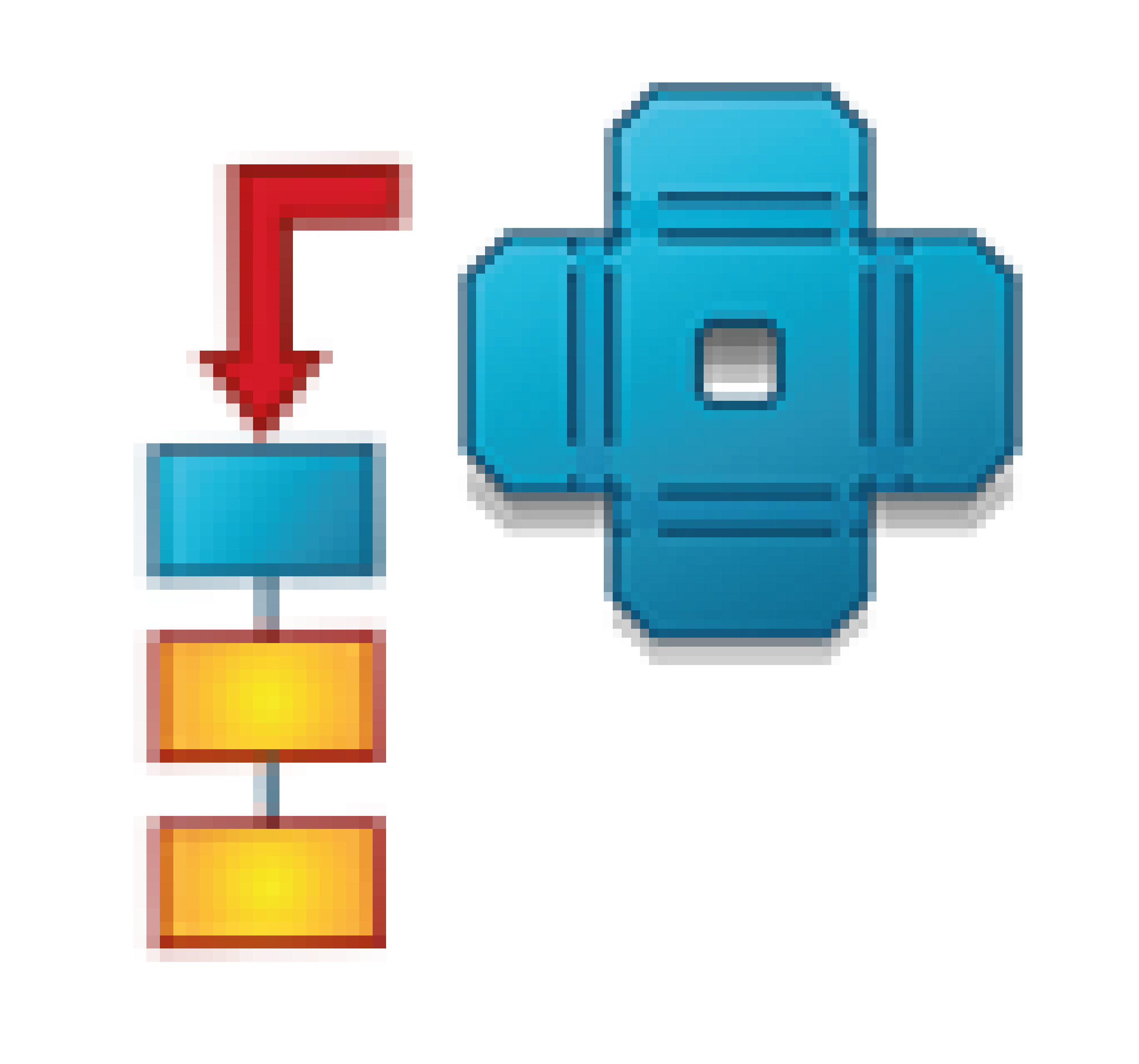
  • Single joint: it creates one joint i the centre of the selected face;

  • Multiple joints: it creates more joints on the selected face. User must type in also the number of joints and the distance of the first one from the selected edge;

  • Multiple equidistant joints: this works as the previous one, but joints will be automatically distribuited in an equidistant pattern along the whole edge;

  • Multiple equidistant joint with distances: this works as the previous one, but user can choose to have a certain distance from the starting edge and the arriving edge

How to use:  compile the form with requested values, then select the male solid, the female solid and the reference face of the male one. In case you are using multiple joint, you must select also the starting edge.
This macro allows you to quickly create one joint between 2 structure, but it can be used also with generic shapes.
How to use:  you must compile the form with joint dimensions (width and height) and an offset value in order to create an hole bigger than the tooth. ZW3D can autodetect the thickness of the structure or ou can compile also this field. Then you must select the male solid, the female one, the reference face and the reference edge.
This macro renames the selected solids according to the rules the user set: he can type a prefix, a suffix and counter.
How to use:  it is enough to run the macro, select the solids and set the rule.
This macro merge 2 different solids into one (with a sharp edge). The benefit to have a single part, will be, for exemple, that you won' t need to add a weldment between them.
How to use:  select the the 2 thickness faces of the solid to merge. These faces must be of the same length, otherwise the longer one will be reduced with a relief.
This macro delete the internal and external radius of a bend,replacing the radius with a sharp edge.
How to use:  user must only select the internal OR the external radius.
This macro creates the internal and external radius on a sharp bend in once.
How to use:   you set the internal radius and the thickness of the sheet metal, then you must select the internal sharp edge.
This macro creates the bend relief on a sharp edge, these are needed to add the radius to the bend and prepare it for the unfolding process. Pay attention because using this macro, you will lose every older feature of the history tree
How to use:  select the reference face and the edge where you need the reliefs the dimension of the reliefs will be automatically calculated basing on the thickness of your sheet metal part, but you can manage an offset to increase the relief dimensions.
This macro automatically creates one rectangular slot in the bend zone, near to the selected hole. The slot length is the same as the hole diameter.
How to use:  the user must select the reference face, ZW is unfolding the sheet metal solid and then the user must select the shorter edge of the bend and the contourn of the hole. If he wants to use this macro on a STEP (or other external file), the user must use the “Mark Bend” function before using this macro.
This macro automatically creates a relief on every selected vertex. The selected points must be on the same plane.
How to use:  you must type in the relief dimension and click the points where you needs the reliefs.The selected points must be on the same plane. You can also automatically align the origin to the shape after each relief creation. You must enable this option in case the origin or the shape are rotated, so the solid is not parallel to the original axis.
This macro creates a GAP on an edge and it can divide the original solid into different ones. This macro can be usefull, for exemple, when you can not execute a certain bend with your bending machine, so you need to divide the shape.
How to use:   you must set the thickness and you can also add an offset to increase the gap value. Then you hjave to select the external edge of the bend, otherwise the gap will be greater than the expected.
This macro creates one or more rectangular holes on a bend zone, in order to let the operator manually fold that flange. you can create a single centred slot or more equidistant slot. the distance between them will be automatically calculated by the macro. In case the part was designed with an other software, you can mark the bends directly with this macro.
How to use:   you must set your choise and compile the corresponding field:
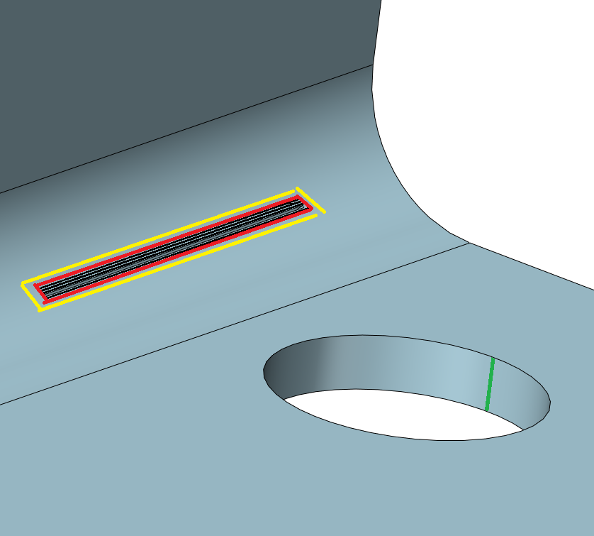
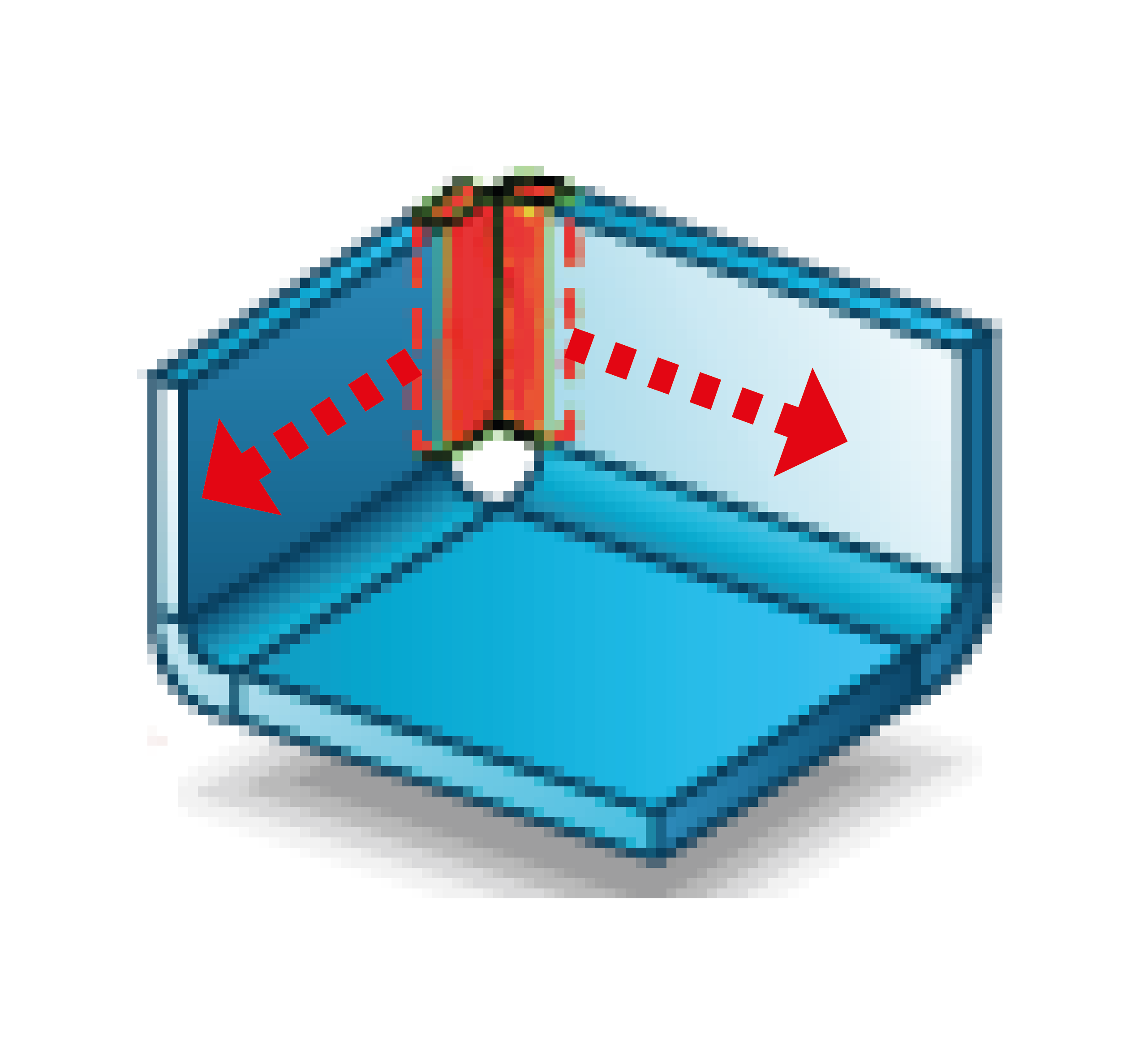
  • single centred slot: set the width of the slot and the dimension of the portion of material you want to keep;

  • multiple slot: set the width, the number of slots and their length.

Choose if you want to mark the bends and then select the reference face and the bend face.
This macro allows the user to convert a generic shape into one or more sheet metal parts.Without this macro, the user should add relief, radius and split the shapes manually or in some cases he should draw the part from 0.
How to use:   set the bend radius and the thickness.Select the edges where you need the external radius, the internal radius, and the slits.Select the faces of the solids that you want to keep in order to split the shape. The created solids will not be linked to the original solid.
This macro is used to quickly create a sheet drawing for each component or solid in an assembly. The assembly can be designed with ZW3D but also with another CAD.
It manages 4 different type of sheet drawing:
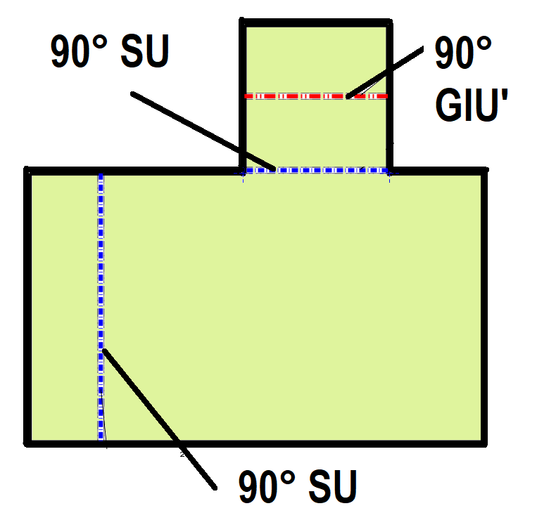
  • Flat pattern view with bend datas;

  • Flat pattern view without bend datas;

  • 3 standard view + ISO view + flat pattern view with bend datas and the flat pattern view without data in a second sheet (as AUTO SHEET DRAWING macro);

  • Flat view of a plate

Meanwhile it is creating the 2D drawings, this macro can:
  • Set a certain material and detect the thickness of the part;

  • Save directly the DXF file in a specified folder;

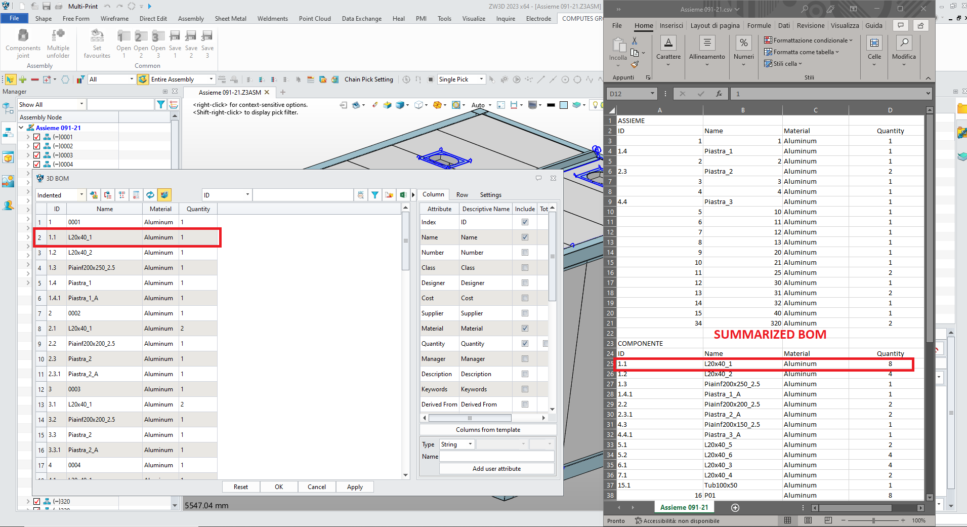
  • Create a CSV report containing information about the parts in the assembly (code, material, thickness, quantity, DXF path…). This file will be useful to have a report of what I did but it can be imported for example in a CAM application.

How to use:   compile the form with your choices and select the first component or solid in the assembly. It will be opened and now you must select the reference face. The macro is now creating the requested type of sheet drawing, then ZW is going back on the assembly and the unfolded part will disappear, so you can select the next one..
This macro in order to work needs a 3D parametric part and a CSV file that contains one or more configurations for the model. The excel file can be saved, for example, from your ERP. Each configuration is a row and can contain more parameters, these correspond to the variables of the 3D model. This macro will create a different DXF for each row, with the correct parameters. The first row of the excel file is not the used data but it only contains the name of the variables. If the customer has Computes Cut Sphera, this macro can directly export the parts into it. He can add to the 3D model and to the CSV other parameters such as material, thickness and quantity, these will be read by the CAM application.
How to use:   select the csv model exported from the ZWPRT, the CSV that contains the configurations and the 3D parametric model. Then ZW will create every DXF by itself, meanwhile the user can manage other activities.Pay attention because it is not needed that the variables inside the 3D model and inside the CSV have the same name, because the only important thing is their order (index).
This macro creates a 2D sheet drawing containing the flat pattern view for each STEP file that is present in the selected folder. The user can also set a certain K factor which will be used during the unfolding process. Pay attention because this macro always uses a face on the XZ plane.
How to use:  it is enough for the user to run the macro, type the K factor and select the proper folder which contains some files.
This macro aligns the selected face of a solid to XZ plane. ZW will automatically move and rotate the whole solid. This macro is really useful to prepare a lot of sheet metal step files and then use the “AUTO UNFOLDER”.
How to use:  it is enough to run the macro and select the reference face.
This macro export the summarized BOM that you configured before with ZW3D standard function "BOM", below the assembly section. Summarized means that if component ABC is present in more different subassembly, its quantity will be summarized.

With classic BOM function, the quantity is summarized only if component that are repeated in the same subassembly.
How to use:  configure the BOM with classic ZW3D function, then run this macro and chose where to save the CSV file.

2D MACROS

This macro adds the flat pattern view of an already unfolded part into the current sheet drawing.
How to use:  it is enough to press this button.
This macro allows to hide the bend data from a flat pattern view. The user must choose if he wants to remove all the data (bend and tangent line) or to keep only the bend lines with their characteristics.
How to use:  confirm the request pressing “OK”, then select the view with a single click and choose one of the 2 proposed options.
This macro adds the isometric coloured view of the corresponding 3D part into the current sheet drawing.
How to use:  it is enough to press this button
This macro adds the code of the part as a text in 0.0 on the marking layer. This macro is useful for who mark the code of the part with maybe with a laser machine
How to use:  select the reference face and press [YES] to mark the bends, [NO] to use the flat command or [CANCEL] to only create the 2D drawing (the part was already unfolded). The flat pattern view will follow the configuration of your favourite template.
This macro save the DXF file of the current 2D drawing in the specified path. The name of the file is read from the linked 3D model and user can not modifie it. It saves also a CSV file that contains some information as: name, material, thickness (are read from 3D model), quantity, priority (always 100), complete path and data-time of the saving.

This macro is really usefull to keep a report of what is done, but also in order to quickly import the developed parts inside a CAM application.
How to use:  run the command and choose where you want to save the DXF and the CSV. You must type the requested quantity and, in case the 2D draing is not linked to any 3D part, you must compile also the material and the thickness.
This macro works exactly as the previous one, but it allows you to change the name of the DXF file.
How to use:  run the command and choose where you want to save the DXF and the CSV. You must type the requested quantity and, in case the 2D draing is not linked to any 3D part, you must compile also the material and the thickness. You must compile material and thickness even if you already saved the 2D drawing with "SAVE DXF AND CSV"
This macro works exactly as "SAVE DXF AND CSV" but it automatically creates a subfolder, renaming it as MATERIAL-THICKNESS of the 3D file associated to the drawing.
How to use:  please follow the same procedure as for "SAVE DXF AND CSV"
This macro works exactly as "SAVE AS DXF AND CSV" but it automatically creates a subfolder, renaming it as MATERIAL-THICKNESS of the 3D file associated to the drawing.
How to use:  please follow the same procedure as for "SAVE AS DXF AND CSV"

TRY THE FULL "SHEET METAL MACROS" SUITE NOW FOR FREE FOR 30 DAYS

38 quick commands and automations to speed up and simplify your job like never before!

Fill out the form and receive the free trial instantly!

Worldwide Standard

For zw3d retailers

Exclusive limited-time offer
for best ZW3D resellers

500 €

Lifetime for each seat
38 Sheet Metal Macros
On demand assistance and training
for you and your customers

CONTACT TO BUY
SEDE LEGALE: VIA ANCILLOTTI, 8 29122 PIACENZA - (PC) - ITALIA P.IVA/C.FISCALE: 01801720333 REA: PC - 192404 PEC: COMPUTESGROUP@PEC.IT
Privacy policy
chevron-down